Open Nav


I. IntroductionIn the previous article, we introduced the three primary methods of soft ground...
I. Introduction: Why Does the Vibratory Hammer Seem Fine, Yet the Job Still Doesn’t Go Smoothly?...
As mentioned earlier, there are three main methods for improving soft soil foundations, and the dy...
Soft ground improvement, also known as soft soil treatment or soft foundation stabilization, refer...

CTT, Drillmaster is coming! Let's meet in Moscow!Booth No.: #3-425Date: 26th Ma...
On pile foundation and steel structure job sites, many project managers have faced the same frustration:
The equipment configuration looks decent—on paper, the parameters even look “impressive”—yet once work actually starts, something just doesn’t feel right.
The vibratory hammer is brand new, with plenty of exciting force.
The crane’s rated capacity is not small.
On the spec sheet, everything looks more than sufficient.
But once on site, problems start appearing one after another:
Lifting feels heavy and sluggish; movements are slow, and operators hesitate to speed up
Vibration starts slowly, amplitude fails to build, and driving efficiency never improves
The crane keeps triggering alarms; even small changes in working radius force shutdowns
The site looks busy, but real progress is constantly interrupted by “waiting, stopping, and adjusting”
These situations often lead to instinctive conclusions:
“Is the vibratory hammer too small?”
“Should we switch to a larger crane?”
Yet across many real projects, the root cause is rarely that the equipment is “not big enough.”
More often, the problem is that the equipment simply does not work well together.
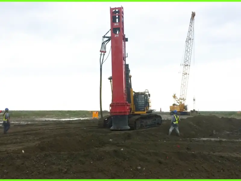
A vibratory hammer is never a standalone machine that can operate independently of its carrier.
Every vibration, every downward force, every start and stop is transmitted through the lifting point, wire ropes, boom, and hydraulic system—forming a single, integrated load and power system with the crane.
In other words, the performance of a vibratory hammer only truly exists within the crane system.
If the crane’s rated capacity does not match the hammer’s dynamic loads,
If the hydraulic system cannot stably supply the required pressure and flow,
If the lifting system lacks sufficient redundancy for vibratory conditions,
Then no matter how good the individual equipment specifications look, on-site performance will inevitably be compromised.
This is precisely why many job sites suffer from low efficiency without a clear explanation.
True construction efficiency has never come from simply putting together two machines that “seem sufficient.”
It comes from system-level matching and coordinated operation between the vibratory hammer and the crane.
That is why this article does not focus on isolated questions such as “how big should the hammer be” or “how many tons should the crane be.”
Instead, it addresses a more easily overlooked yet decisive logic:
“1 + 1 > 2” is not achieved by stacking parameters—it is achieved through coordination.
In vibratory hammer selection discussions, one statement is heard over and over again:
“This crane has enough tonnage—it can definitely do the job.”
But anyone who has actually worked on site knows that “being able to lift” and “being able to work stably and efficiently” are two completely different things.
The rated lifting capacity on a crane nameplate is a static reference value under ideal conditions.
Vibratory hammer operation, however, involves continuous dynamic loading and constantly changing working conditions. This is exactly why many projects run into limitations on site even when the “paper tonnage” looks fine.
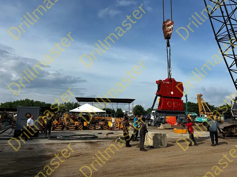
Before evaluating whether crane tonnage is adequate, the first step is not to look at the hammer parameters, but to understand what the crane is actually carrying.
That load is far more than just the hammer itself.
(1) Self-weight of the vibratory hammer
This is the most obvious component—and often the only one people consider.
(2) Weight of clamps and accessories
Including pile clamps, connection flanges, damping structures, etc.
In medium to large vibratory hammer systems, these components often weigh several hundred kilograms or even over one ton, yet are frequently underestimated or ignored.
(3) Pile weight (including skin friction–induced additional load)
This is where problems most often occur.
Beyond the pile’s own weight, friction between the pile and soil during driving or extraction acts as an additional load on the crane system. In clay layers, long piles, or deep installations, this added load often far exceeds intuitive expectations.
(4) Dynamic load and vibration amplification factors
Vibratory hammer work is not static lifting.
During start-up, shutdown, resonance crossing, or sudden pile release, significant dynamic load amplification occurs. These forces are not reflected in static weight calculations, yet they directly test the crane’s true capacity.
In reality, the crane is handling a dynamic, composite, continuously changing load system.
Many accidents and efficiency problems are not caused by incorrect equipment selection, but by insufficient redundancy.
(1) Dynamic load amplificationunder vibration
Loads during vibration are not linear or smooth.
Short-term impact forces and uneven load distribution push the crane to operate near its limits for extended periods. This reduces efficiency, triggers protection systems, and increases structural fatigue risk.
(2) Effects of slewing and luffing on lifting capacity
Rated capacity applies only at specific boom lengths and radii.
On site, cranes inevitably slew, luff, and adjust positions. As working radius increases, available lifting capacity drops rapidly. Many “sudden alarms” occur during these seemingly routine operations.
Put simply:
If a crane is already working at the edge of its limits, any change in operating condition removes all remaining margin.
(1) Recommended safety factor
In vibratory hammer operations, common practice is:
Crane rated capacity ≥ 1.3–1.5 × the maximum working load of the vibratory hammer system.
For long piles, deep installations, complex soil conditions, or high-frequency vibration, this safety factor should be increased further.
(2) Empirical matching logic for different pile types
Short, lightweight sheet piles: can approach the lower limit, but dynamic loads must still be considered
Long steel pipe piles or H-piles: friction-induced loads must be carefully evaluated
Deep water, soft soils, or high-friction strata: crane tonnage should be clearly above theoretical calculations
A reliable selection philosophy is never “just enough,” but “always with margin.”
One-sentence takeaway:
When crane tonnage is wrong, the problem is rarely “can’t lift”—it’s “lifting too close to the edge.”
When troubleshooting vibratory hammer performance, many projects follow the same path:
Poor vibration → suspect the hammer → adjust parameters, change clamps → even consider replacing equipment.
After all that effort, the problem often remains.
In many cases, the real issue lies not in the hammer itself, but in the hydraulic circuit behind it.
A vibratory hammer is fundamentally an actuator that depends heavily on stable hydraulic output. If the system cannot supply enough oil, cannot supply it stably, or cannot sustain the load, even the highest exciting force will remain a number on paper.
To judge compatibility, you must first understand what the hammer truly needs.
(1) Operating pressure range: “reaching it” is not enough
Vibratory hammers have a defined stable operating pressure range.
Insufficient pressure prevents the excitation system from reaching its design state.
Pressure fluctuations cause intermittent vibration and obvious efficiency loss.
Many crane auxiliary circuits show normal pressure under no-load testing, but once continuous vibration begins, pressure drops or fluctuates—one of the main causes of unstable performance.
(2) Rated flow: determines how strong and how sustainable vibration is
Flow directly affects vibration frequency and amplitude.
Insufficient flow leads to:
Inability to reach target frequency
“Soft,” sluggish vibration response
Penetration efficiency far below expectations
Unstable flow causes vibration strength to fluctuate, slowing pile driving and accelerating equipment wear.
(3) Cooling and return capacity: the hidden bottom line of continuous work
Vibratory hammers are high-energy, continuously operating hydraulic devices.
Restricted return lines or insufficient cooling lead to rapid temperature rise. Short runs may be tolerable, but efficiency degradation during continuous operation is almost inevitable.
Hydraulic mismatch rarely appears as “completely unusable.”
More often, it shows up as familiar, seemingly unrelated issues.
(1) Vibration frequency cannot reach rated value
The system starts normally, but frequency never reaches nominal levels—often mistaken for insufficient hammer power when the real cause is limited flow.
(2) Slow start-up and insufficient amplitude
Start-up requires instant, stable pressure and flow. Slow auxiliary circuit response causes delayed, weak vibration, severely affecting initial penetration.
(3) Overheating and efficiency decay
After continuous operation, vibration performance degrades or forces shutdown for cooling—usually because the crane’s hydraulic system was not designed for prolonged high-load vibration.
Many assume: “If the crane is big, the hydraulics must be fine.”
Reality often proves otherwise.
(1) Huge variation in auxiliary circuit capability
Main crane hydraulics serve lifting, luffing, and slewing.
Vibratory hammers rely on auxiliary circuits, which vary widely in flow, pressure, and continuous duty capability between models and configurations.
(2) Interface and output differences across crane brands
Interfaces, control logic,and pressure regulation methods are not standardized.
Some cranes show “sufficient parameters” in manuals but are limited by valve design or protection strategies, preventing stable long-term output. This explains why the same hammer performs very differently on different cranes.
Before equipment arrives on site, confirm:
Continuous auxiliary circuit pressure range
Actual usable rated flow (not peak flow)
Return line diameter and allowable back pressure
Cooling capacity and permitted continuous operating time
Hydraulic interface type and control compatibility
Miss one item, and you’re likely to hit a problem on site.
When is an independent power pack necessary?
Strongly consider one if:
Crane auxiliary flow or pressure is clearly insufficient
Long-duration, high-frequency vibration is required
High ambient temperatures or strict stability requirements apply
Multiple cranes are used, or crane models are not fixed
The value of an independent power pack is not “one more machine,” but a stable, controllable, dedicated hydraulic source that allows the vibratory hammer to perform as designed.
One-sentence summary:
Many vibratory hammers “don’t work well” not because they are weak—but because the hydraulic system holds them back.
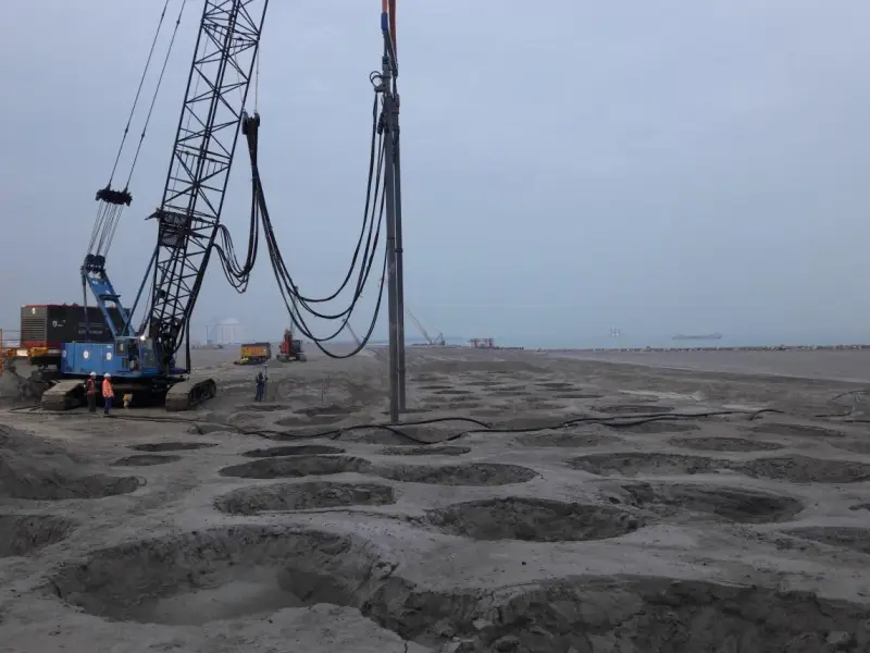
Stability = Safety + Efficiency
On many sites, stability is treated as a purely safety concern: “As long as there’s no accident, it’s fine.”
In vibratory hammer work, stability determines not only safety, but also efficiency and equipment wear.
Only a stable lifting system can transmit vibration energy effectively into the pile.
In an unstable system, even high exciting force is wasted on sway and displacement.
Stability is the result of multiple interacting variables.
(1) Boom length and working radius
As boom length increases and radius grows, stability margins shrink rapidly.
Under vibration, this effect is amplified—what feels stable at short radius can become visibly unstable at longer reach.
(2) Lifting point height and center of gravity
A vibratory hammer + pile forms a tall, slender, high-center-of-gravity system.
The higher the lifting point, the greater the swing radius. Small vibrations are magnified into noticeable sway, which is why stability varies drastically with pile length.
(3) Lateral forces and vibration-induced sway
Vibration is not purely vertical.
Uneven soil, pile eccentricity, or clamping deviation generate periodic lateral forces. If crane stability is insufficient, these forces translate into sway, consuming system energy.
Instability affects far more than appearance.
(1) Pile position deviation
Even slight lateral movement during driving can cause pile misalignment, affecting accuracy and slowing subsequent work.
(2) Off-axis vibration and uneven wear
Unstable conditions prevent vibration from staying aligned with the ideal axis, leading to:
Localized overload on clamps
Uneven wear of bearings and eccentric blocks
Shortened maintenance intervals
Many cases of “abnormal wear” stem from instability, not manufacturing defects.
(3) Fatigue of crane structure and hydraulics
Continuous sway and impact place the crane under non-design loads, increasing hydraulic stress and accelerating structural fatigue—an invisible but costly long-term burden.
(1) Control safe operating radius
Experience shows that during vibratory hammer work:
Operate at smaller radii whenever possible
Avoid long-term work near the crane’s capacity curve limits
Proactively reduce radius for long piles or high-frequency vibration
Stability often comes from leaving margin.
(2) Reduce vibration impact through configuration
Optimize lifting point position
Use appropriate damping and shock-absorbing elements
Choose suitable wire rope lengths and layouts to avoid pendulum effects
Adjust work rhythm; avoid frequent abrupt starts and stops
These measures cost little but deliver substantial stability improvements.
One-sentence takeaway:
The true capability of a vibratory hammer is only released within a stable lifting system.
This is not optional—it is a red line
In vibratory hammer operations, safety is not an added condition; it is the prerequisite for the system’s existence.
The hammer-crane combination involves high energy, high dynamic loads, and high risk. Underestimating any lifting link can result not just in lost efficiency, but in equipment damage, personal injury, or irreversible accidents. That is why lifting safety standards are not a matter of experience—they are an absolute bottom line.
System reliability is determined by its weakest component.
(1) Selection of hooks, wire ropes, and shackles
All lifting components must be selected for dynamic loads, not static weight.
Wire ropes must consider fatigue life under vibration, not just breaking strength
Shackles and connectors must have clearly defined rated loads and working angles
Never mix uncertified or non-application-specific components
Many accidents originate from small, seemingly insignificant parts.
(2) Anti-rotation and anti-drop measures
Vibratory hammers generate inevitable rotational tendencies and impact loads.
Without proper anti-rotation and anti-drop design:
Wire ropes may twist or kink
Connectors may loosen under vibration
Pile attitude becomes uncontrollable
Once these issues occur, there is rarely time to react.
The key difference from ordinary lifting is continuous dynamic loading.
(1) Fatigue failure: the most hidden and dangerous
Fatigue failure gives no warning.
Under continuous vibration, components may develop internal micro-cracks while appearing intact—until sudden catastrophic failure occurs. This is why regular inspection is more important than single-event load capacity.
(2) Instantaneous impact loads far exceeding static calculations
During start-up, shutdown, or sudden pile release, impact loads can far exceed average values. If the system is only “just sufficient,” these moments can trigger accidents.
Even the best equipment needs disciplined management.
(1) Pre-operation checklist (must be assigned to individuals)
Check for wear, deformation, or cracks in lifting components
Inspect wire ropes for broken strands, kinks, or abnormal elongation
Confirm all connections are secured and anti-drop devices engaged
Verify hydraulic and control systems function properly
Inspections are not formalities—they are the site’s last line of defense.
(2) Coordination between operator and signalman
Operators must understand the hammer’s working rhythm
Signals must be unified and unambiguous
Start/stop vibration must be communicated and confirmed in advance
Many dangerous moments arise simply because “everyone assumed the other person knew.”
One-sentence summary:
In vibratory hammer operations, all efficiency gains must be built on an uncompromising safety baseline.
From equipment purchasing to construction-solution thinking
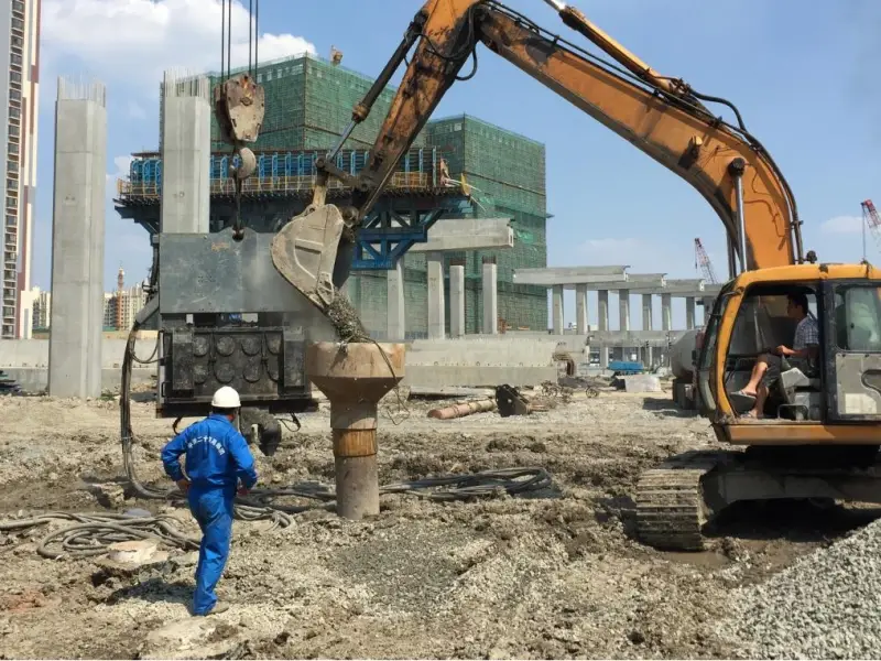
When vibratory hammers and cranes feel awkward together, the issue is often not quality—but that they were never selected under the same construction logic.
A common scenario is:
Each machine looks fine on its own, yet the combination is constrained everywhere.
The reason is simple: system engineering was broken down into individual purchases.
(1) Buying the hammer first, then finding a “usable” crane
This is the most common—and most dangerous—path.
Hammers are chosen based on exciting force, weight, or price. Only after delivery does anyone check crane compatibility. The result:
Crane tonnage barely sufficient
Hydraulic system forced into long-term full-load operation
Severe lack of stability and safety margin
It “works,” but at the cost of constant stress on equipment and personnel.
(2) Focusing on single parameters, ignoring system boundaries
Examples:
Looking only at crane tonnage, not working radius
Looking only at hammer exciting force, not hydraulic demand
Looking only at single lifts, not continuous dynamic loading
When each machine operates near its own limits, the system is most likely to fail.
Reliable selection works in reverse.
(1) Define construction conditions first
Soil conditions
Pile type, diameter, and length
Target depth and construction rhythm
These define the system’s rigid requirements—not equipment brochures.
(2) Evaluate hammer and crane as one system
Can the crane stably carry dynamic loads at the required radius?
Can the hydraulic system sustain required pressure and flow?
Are stability and safety margins sufficient for long-term work?
The question is not which machine adapts to the other, but whether the system is balanced.
(3) Use combined calculation or simulation when needed
For complex conditions or large projects, experience alone is not enough. Joint calculations or simulations can expose system limits early—before risks reach the job site.
(1) When should manufacturers be involved early?
Long piles, deep installations, or high-friction strata
Limited crane options
Tight schedules with high stability demands
A professional supplier’s value lies not only in equipment, but in defining system boundaries.
(2) Why early system analysis saves money
“Pushing through on site” costs show up as:
Low efficiency and extended schedules
Abnormal equipment wear and higher maintenance
Hidden losses from downtime and adjustments
Early system evaluation delivers:
Stable construction rhythm
Predictable equipment performance
Lower overall construction cost
One-sentence summary:
Selecting a vibratory hammer and crane is not a purchasing issue—it is a construction-solution issue.
Looking back at recurring problems in vibratory hammer operations—low efficiency, unstable equipment behavior, constant compromise on site—the common factor is not poor equipment, but a system that never truly ran smoothly.
A vibratory hammer and a crane are not two machines that can be casually combined. Through load, power, stability, and safety boundaries, they form a tightly coupled, dynamically coordinated construction system. Underestimating any link amplifies on site into lost efficiency, hidden risks, or unacceptable costs.
This is why focusing on a single parameter often leads to choices that are “correct on paper but awkward on site.” A system-level perspective, by contrast, enables more stable and efficient performance with more rational configurations.
Many people understand equipment parameters—tonnage, exciting force, pressure, flow.
What is truly scarce are those who can place these parameters into real construction conditions and understand how they constrain and amplify one another.
Those who understand system matching are the ones who truly understand construction.
When vibratory hammer and crane are genuinely aligned in tonnage, hydraulics, stability, and safety margins, job sites no longer rely on brute experience. Efficiency is released naturally, and risk becomes controllable.
That is the most real—and most valuable—expression of “1 + 1 > 2” in engineering practice.
Our professional team will reply you as soon as possible.
 English
  Español
 العربية